
 Google Scholar
You need to calm down, you’re being too loud
Taking a break from exploring k-means on my Apple ][+, I decided to tackle a problem of significantly greater import: the speaker is really loud. I don’t recall this ever bothering me in high school but it’s pretty loud and there is no way to non-programmatically control it. I’d like to have a volume knob so I can play Ultima 1 late at night without waking the dead.
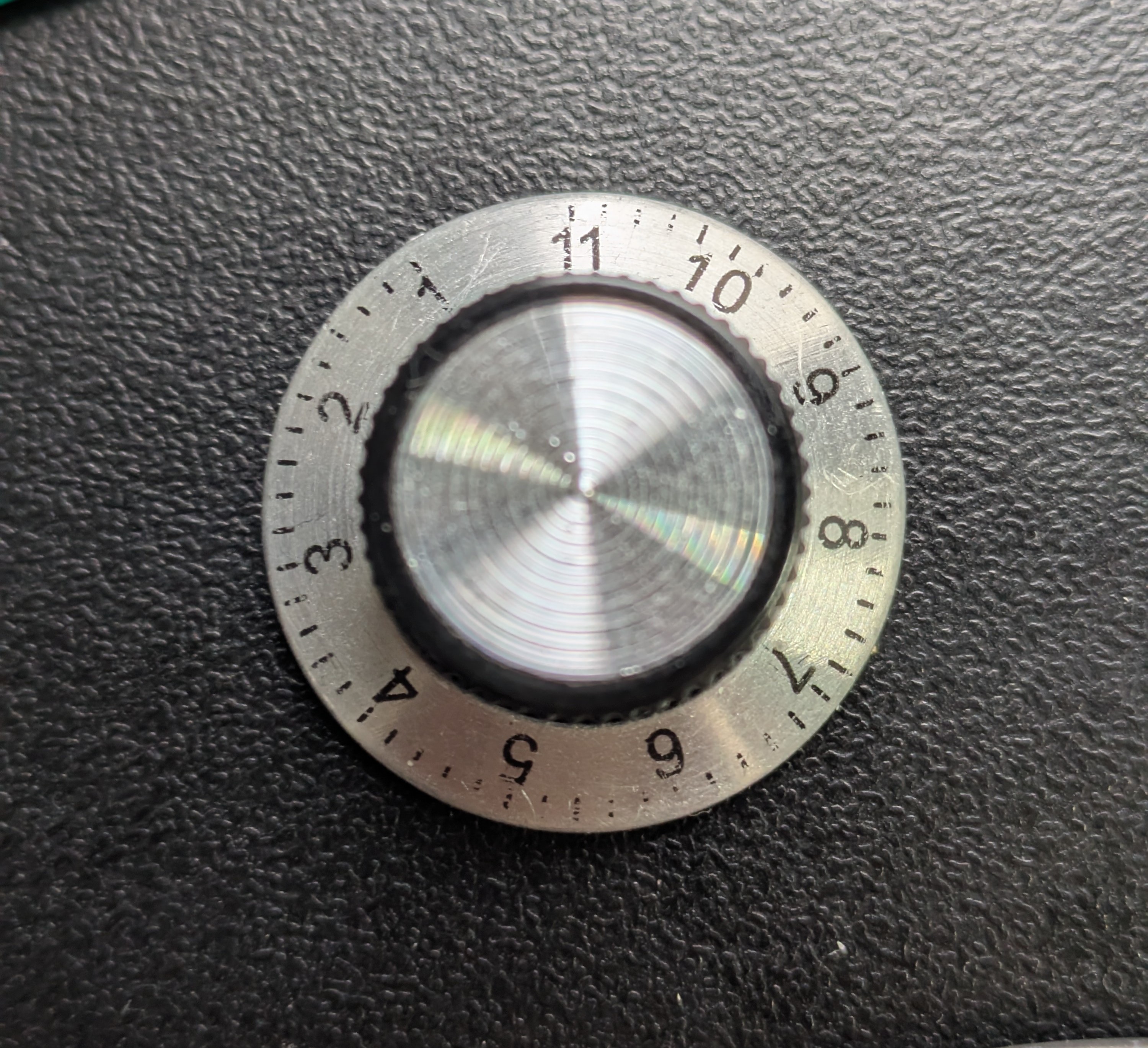
It goes to 11
There’s not a lot of how-to retro hardware upgrade videos on the internet but I found this and it did the trick.
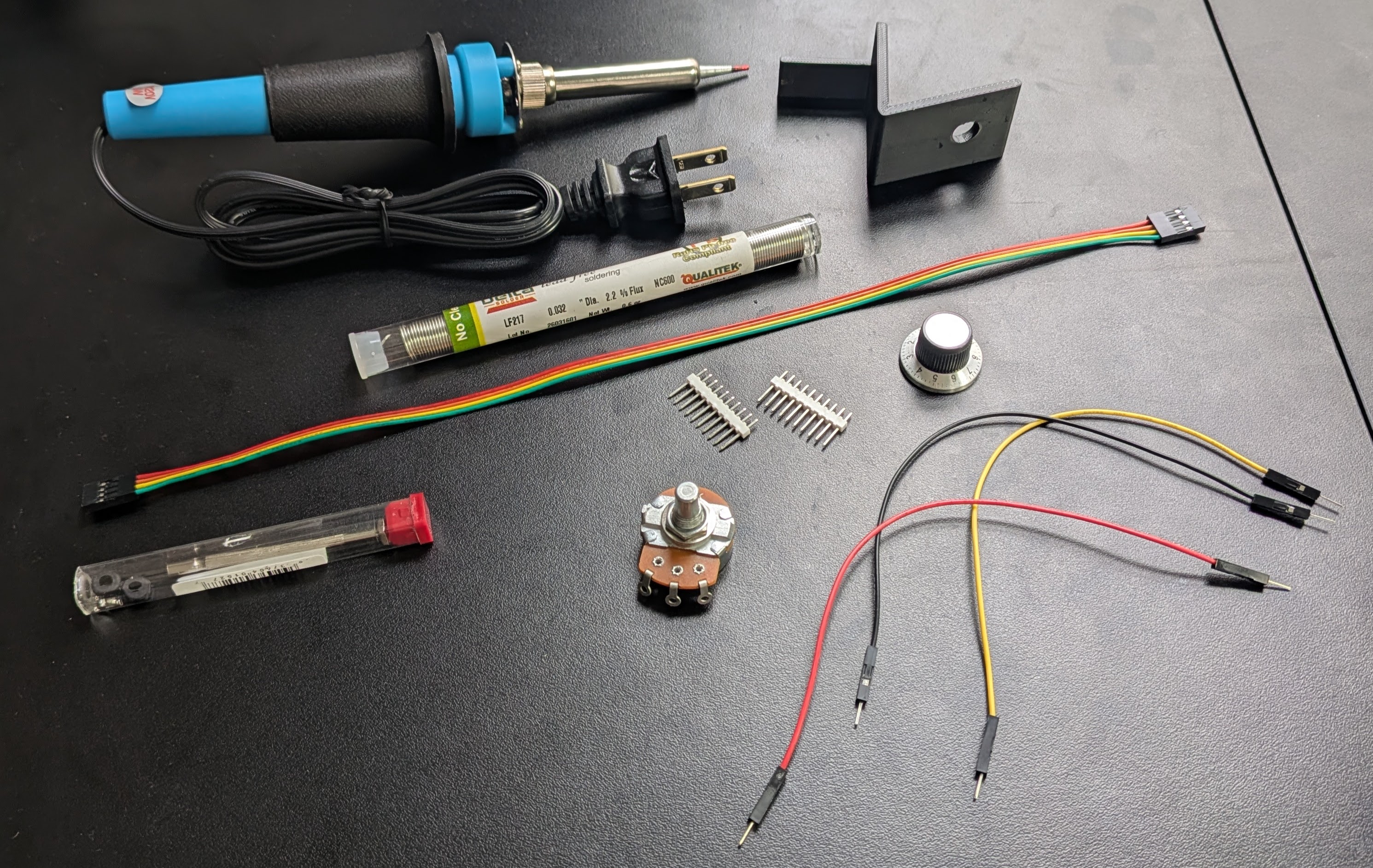
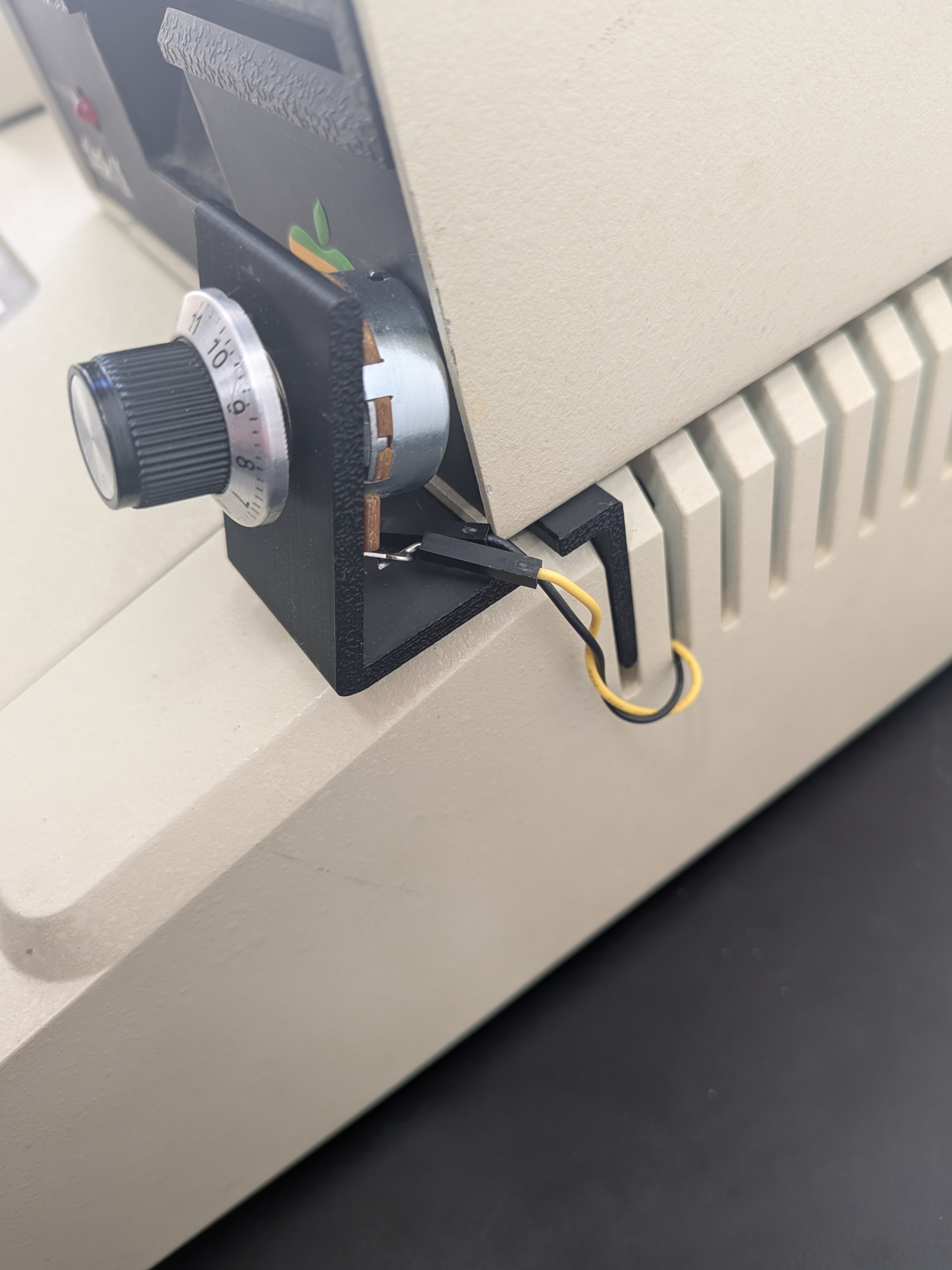
While it’s a little difficult to follow (he offers a schematic but it’s hard to tell which wires are going where), he links to the necessary parts. In addition to a 1kΩ audio log potentiometer, I got a knob that goes to 11 and an STL file to 3D print a small mount for the potentiometer and knob that slides into one of the air vents.
Putting it all together
I’ve been busy with other things but after all the parts arrived (it took a couple weeks for Craftcloud to 3D print and mail the holder) but one afternoon I had a free hour so I decided to slap it together.
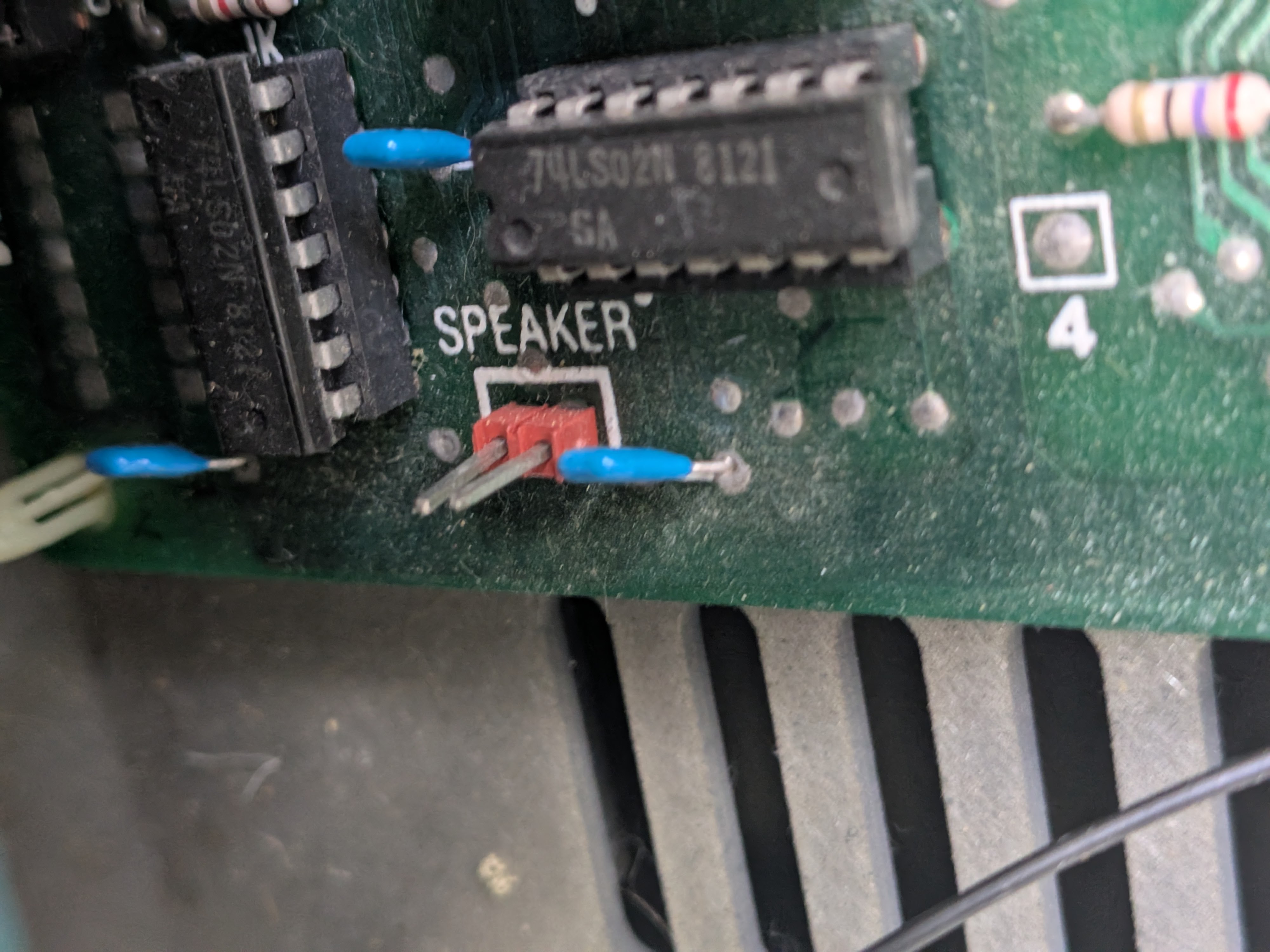
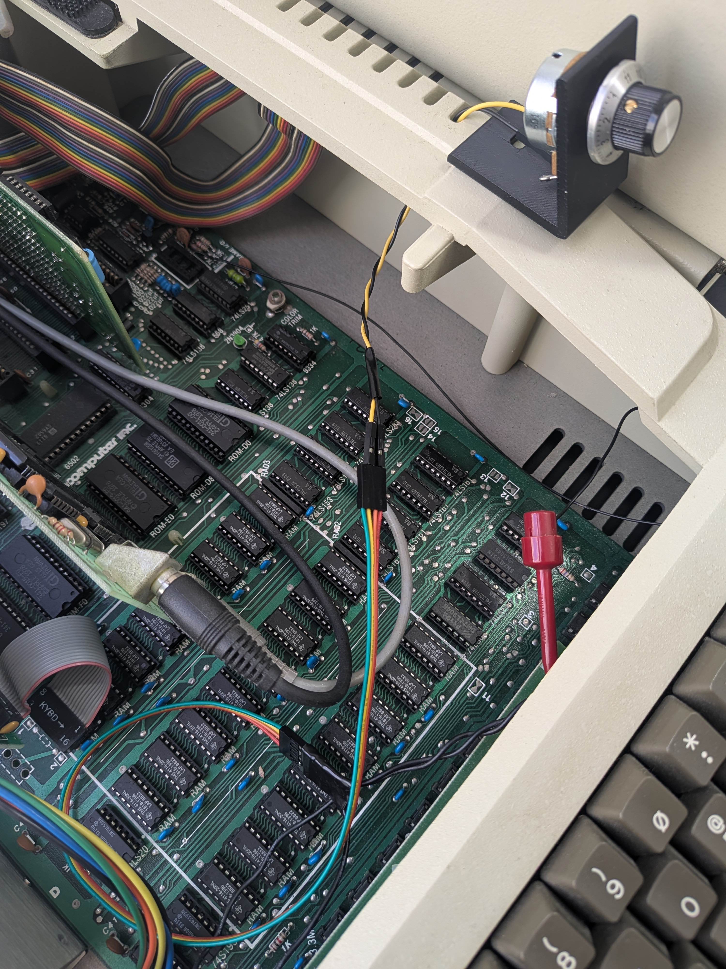
Attempting to follow the video, my first instinct was the “parallel shunt” method, which has the potentiometer run side-by-side with the internal 8Ω speaker. I got a little confused by what connects to where, so I took a look at the speaker jack on the motherboard and, using a multimeter, tried to find ground. One of the pins registered 5.8Ω and the other 0, but ground was on the opposite side than I expected. So, to get a sense of how the neighboring capacitor is wired, I decided to consult the motherboard’s schematic which of course, is included as a foldout at the back of the Apple ][ Reference manual.
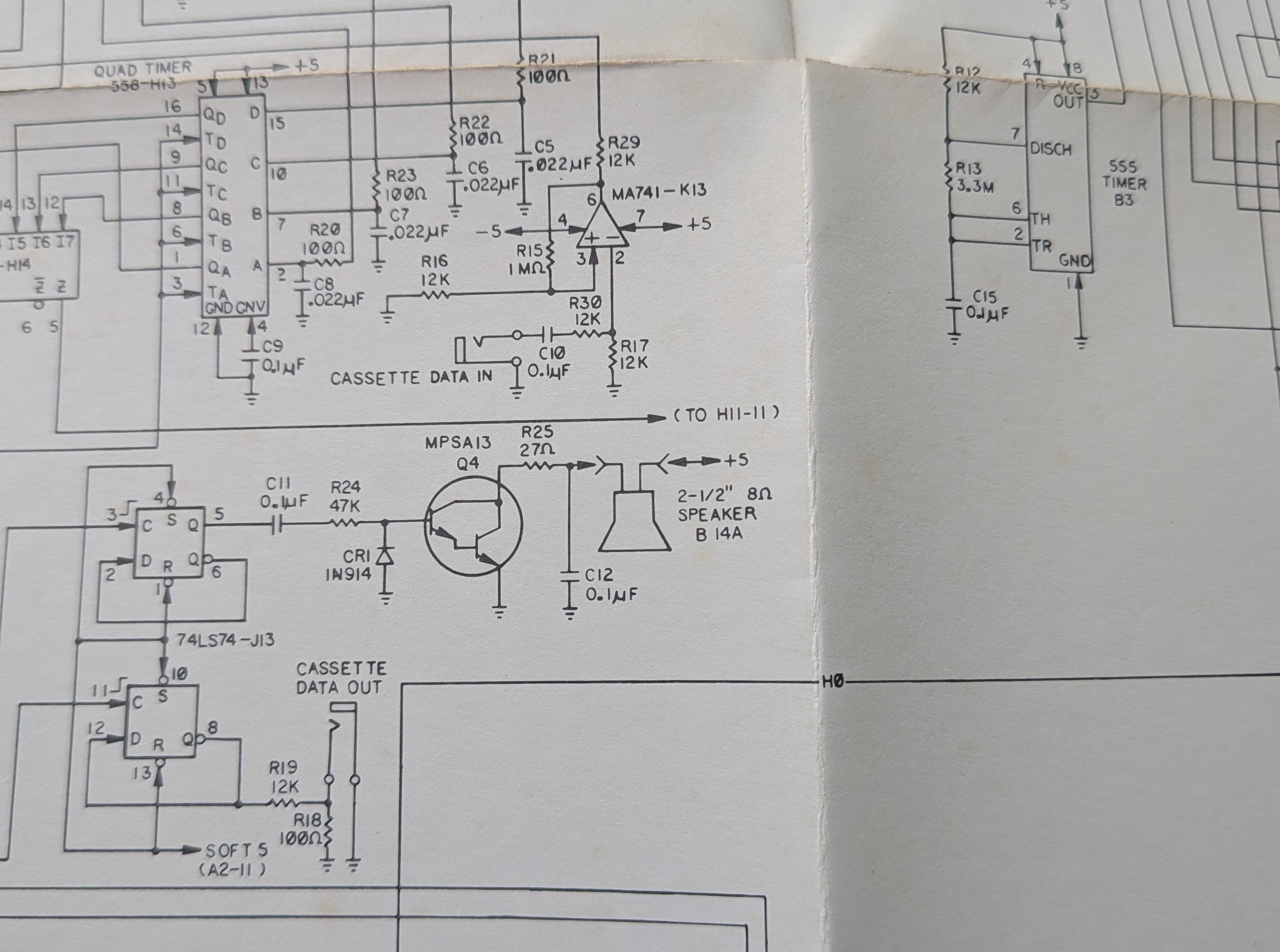
I then realized something surprising: the speaker isn’t tied to ground but, rather, is suspended between the +5V power rail and the collector of the Q4 switching transistor. I now realize that this is what the gentleman in the video was trying to communicate with the on-screen text. I’m guessing that he either belatedly realized the same thing or forgot to mention that while making the video.
While the “parallel shunt” method would provide a smooth volume sweep across the entire turn of the knob, I began to get nervous about frying my vintage machine. Not only could I wire it up incorrectly and connect power to ground, but turning the dial down to zero could create a short forcing the Q4 transistor to pull +5V straight to ground. There’s a way to mitigate the latter risk by adding a safety resistor to either terminal 1 or 2 of the potentiometer.
Rather than take the risk, I opted to mount the potentiometer in series instead, making a short circuit virtually impossible. The downside is that I probably won’t get a full volume sweep across the entire turn of the knob, but that’s not a big deal.
Splicing the wires
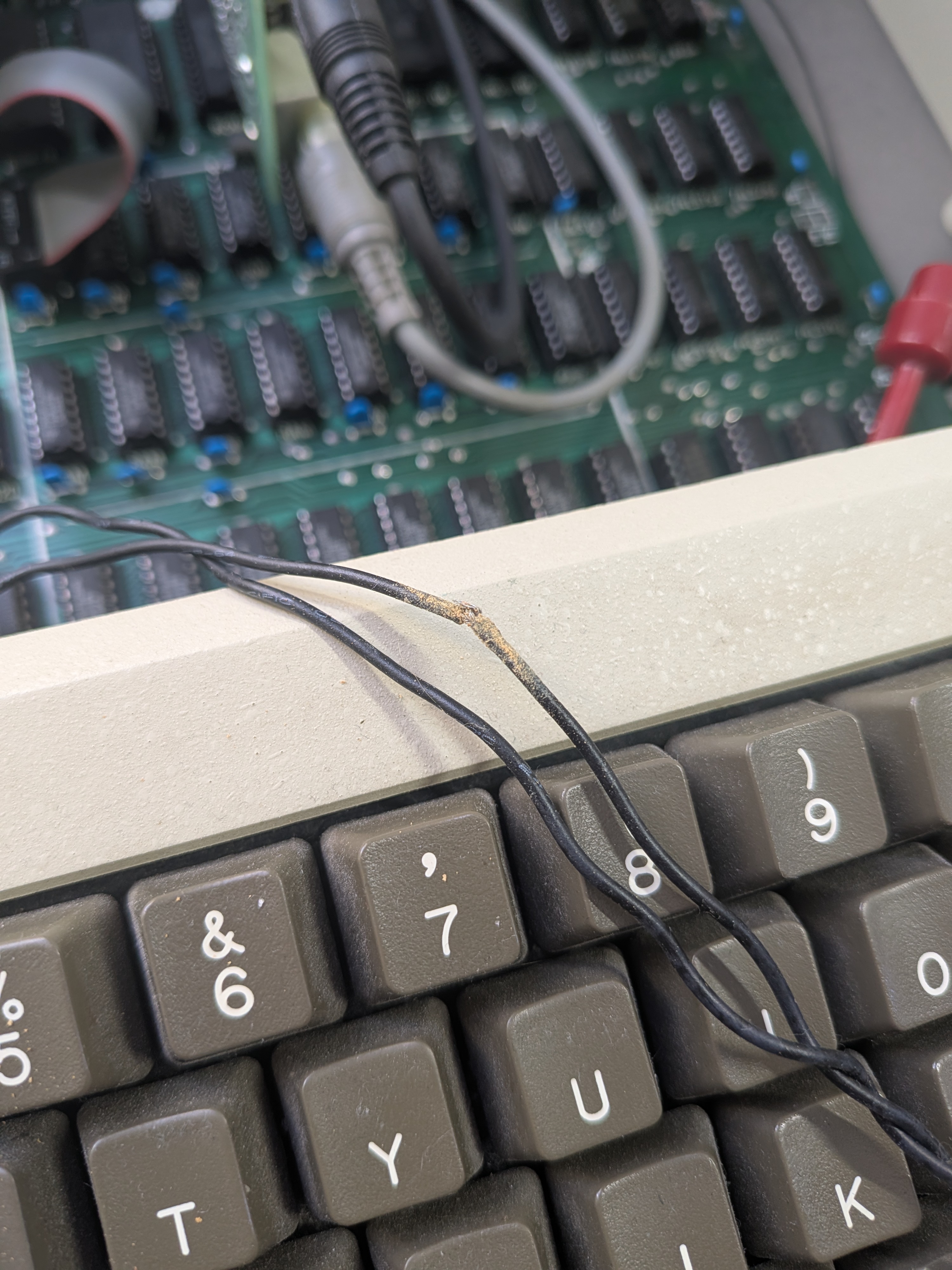
Mounting the potentiometer in series is also a much easier procedure. Rather than wiring up the three terminals on the potentiometer, I only need two. Also, I don’t need to figure out which wire going to the speaker is which - I can splice into either one. Since one of the wires looked like it already had damage, I decided to just snip it there.
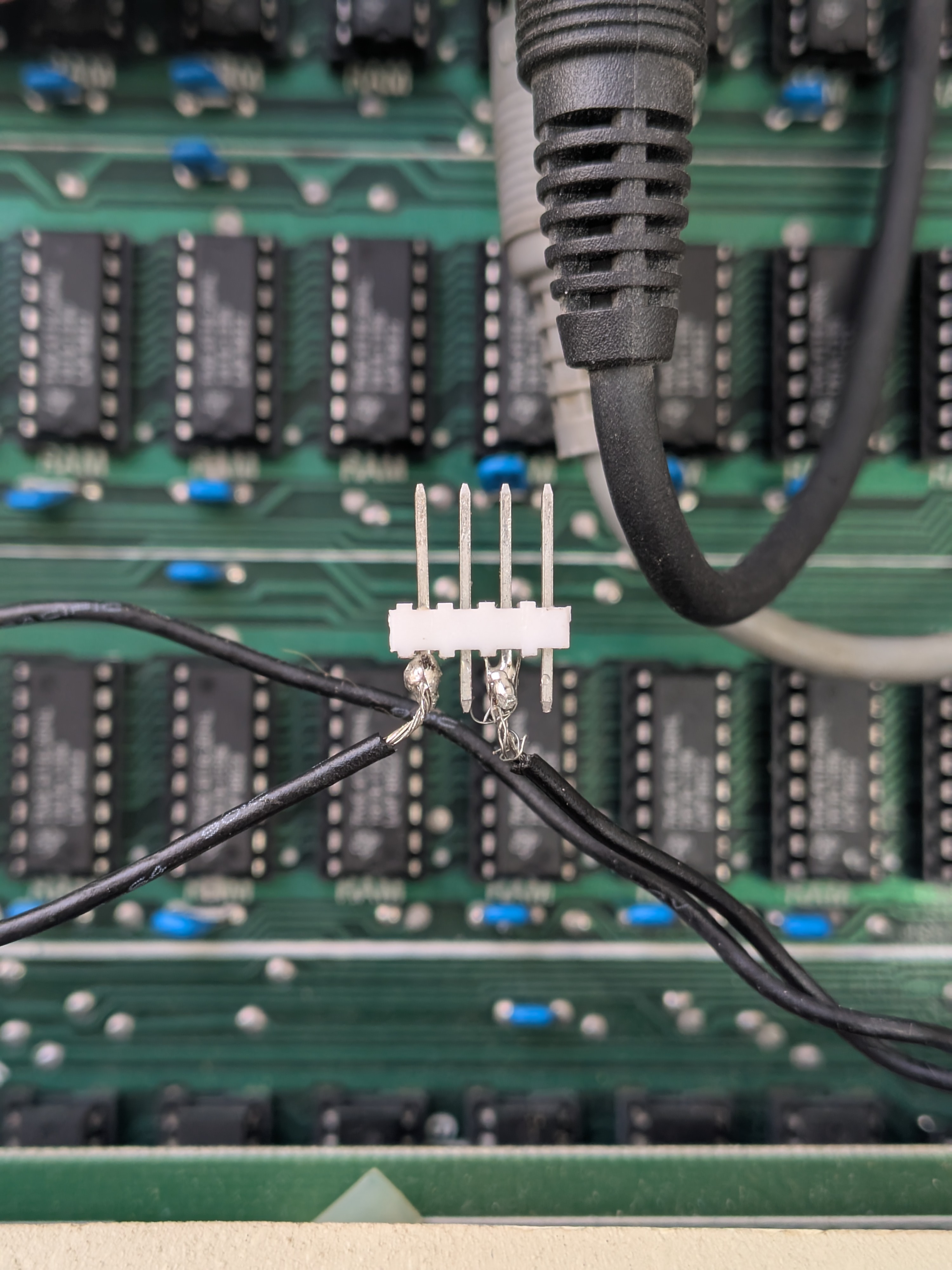
To enable disconnecting the potentiometer, for whatever reason, I used a modular approach with SparkFun 0.1” 4-pin jumper wires and a breakaway male header strip. I used wire snips to cut through the 5th pin of the header strip to get an exact 4-pin section without cracking the plastic housing. My first crack at soldering to the header was ugly, to say the least, but the next one went better. For safe keeping, I then wrapped it in electrical tape.

Mounting the potentiometer
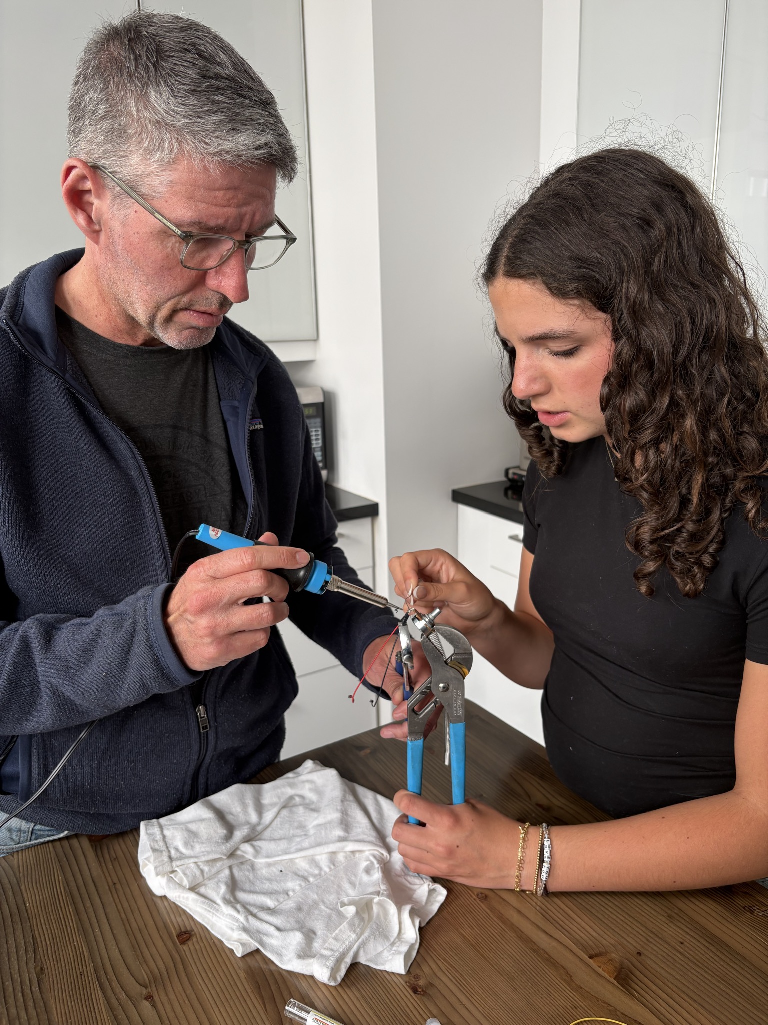
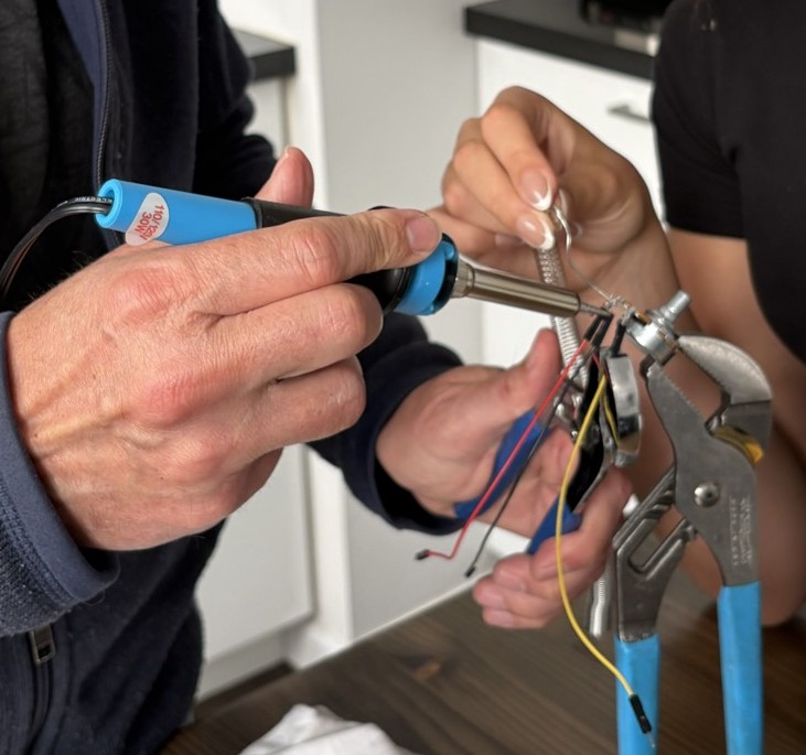
Since the inline series method only requires two terminals, Terminal 1 (the far-left pin when facing the shaft) was left empty. With help from a lovely assistant (who, frankly, I could have used when connecting the header), I soldered jumper wires to the potentiometer. (Terminal 1 was left empty. I originally wired it for the parallel shunt configuration but then removed it.)
From there it was easy. I chose the colors of the jumper cables to line up with the 4-pin jumper wire, but even if I got it backwards the volume knob would just work in the opposite direction. (I didn’t get it backwards.) Sliding the 3D printed mount into the case was easy although I had to bend the terminals pretty severely in order to get them around the floppy drive. And… guess what?
The Verdict
It works! (Turn up the volumn on your computer if you watch the video below.)
As anticipated, the dial does not have a full sweep of volume control. At 11 the sound is as loud as it’s always been but somewhere around 7 it’s pretty much at the lowest level of volume, which is pretty quiet, but it doesn’t go completely silent. All of that is fine. It’s operating as intended and doing the job I want it to do. The turning feels solid and for almost half the knob the audio softens nicely. It’s also easy to remove and a simple jumper cable connecting a couple plugs on the 4-pin jumper wire will get it back to original operation. Most importantly, there is virtually no risk to the motherboard.
Not that there’s a lot of chance of this happening but now at some point it’d be nice to find time to finish Ultima 1!
Leave a Comment